Calibration
We record each joint’s physical limits, check that travel is a normal encoder interval, and map those ranges and directions onto the sim model.
Do this on first hardware bring-up, after replacing a servo, or when travel changed.
Before you start
- Prepare each servo with
solarian calibrate-servobefore you mount it: it sets the ID, resets the comms and position registers, and parks the shaft at mid-encoder so you can fit the horn with the mechanism at mid-travel. That keeps the0/4095encoder seam out of the joint's travel, which is the one thing calibration cannot fix in software. - Assign servo IDs and the serial port in
conf/modules/<module>.yamlfirst —solarian setup-moduleif they are not already set. Servo model and continuous-vs-limited live on the Module class, not in yaml. - Stop
run-robot. The bus can only be open once; every calibrate command talks to the device in-process, the same waysolarian calibratedoes. - Run on the machine the device is wired to (the Pi under a
pideployment; your laptop underlocalhost).
# conf/modules/right_arm.yaml
actuators:
  shoulder_pan:
    id: 1
    port: ${actuator_port}
    # written by solarian calibrate:
    # real_range_min / real_range_max / center_offset / drive_mode
The command is interactive. solarian calibrate lists every module on your Robot and Controller and asks which to calibrate.
Calibrate an arm (SO-106)
Example: the SO-106 project, module right_arm.
solarian calibrate # pick right_arm
The console uses the same step titles as this page. Answer ENTER / Y / N in the sim window when it is open (the terminal also works).
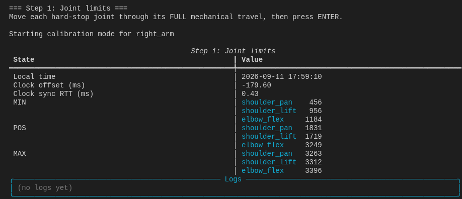
Step 1: Joint limits
Move every hard-stop joint through its full travel. Continuous joints (wrist_roll on SO-106) are printed and skipped — they have no hard stop.
The status board shows MIN / POS / MAX. POS is the raw encoder. A single wrap-looking glitch is ignored.
If travel crosses the encoder seam
Travel that straddles 4095→0 is rejected, and the command walks you through fixing it on the spot. No offset can help: the servo computes Goal - Present in raw counts with no wraparound, so a goal on the far side of the seam drives the wrong way into a hard stop and overloads. An offset — software center_offset or the hardware Homing_Offset register — is a translation, so it moves the discontinuity without removing it.
The only fix is to rotate the horn on the shaft:
- Remove the horn / linkage from the joints the command lists.
- Confirm the shaft turns freely; the command then drives it to mid-encoder (
2048), which can be most of a turn. - Refit the horn with the mechanism at mid-travel (half open, for a gripper).
- The limit sweep restarts, and now saves
center_offset: 0.
Step 2: Home position
The sim opens parked at model q=0 — not a live copy of the real arm (mapping is not done yet). Match that pose by hand. It is mid-travel for hard-stop joints and the zero we store for continuous wrists. Leave a little room so any joint can still move a few degrees either way.
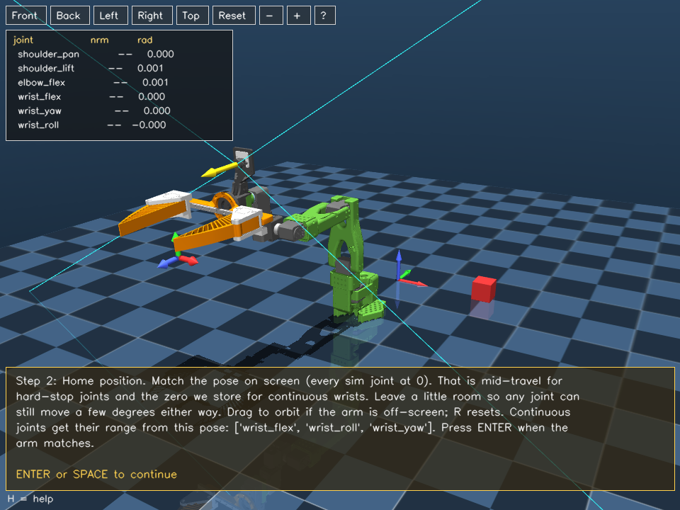
Press ENTER in the sim window when the real arm matches.
Step 3: Sim mapping
The sim now follows the real arm. For each joint a red arrow marks the hinge axis. Move that joint. If the sim goes the other way, answer N and we flip drive_mode.
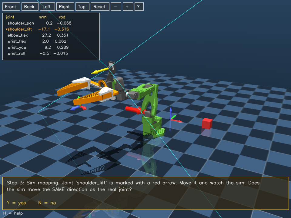
This is the only direction question. There is no “which encoder end is min.”
Output
Values are written to conf/modules/right_arm.yaml and to the servos (or applied in software on buses with no homing register).
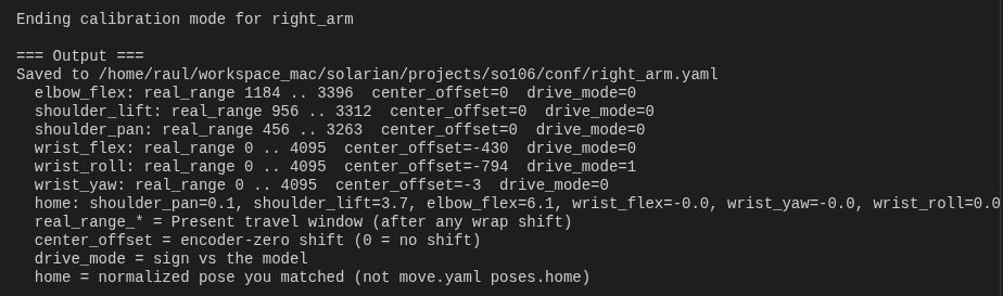
| Field | Meaning |
|---|---|
real_range_* | Travel window in encoder counts |
center_offset | Encoder-zero shift. 0 after a sweep; non-zero only from set_half_turn_homings on a continuous joint |
drive_mode | Sign vs the model (0 or 1) |
home | Normalized pose you matched. Not move.yaml poses.home |
# conf/modules/right_arm.yaml — after solarian calibrate
actuators:
  shoulder_pan:
    id: 1
    port: ${actuator_port}
    real_range_min: 452
    real_range_max: 3255
    center_offset: 0
    drive_mode: 0
home:
  shoulder_pan: 2.4
  # ...
After save, the sim stays open and follows the real arm. On-screen nrm is the real normalized pose; rad is the sim joint angle. Move the arm, then press ENTER when you are done.
Check spans later:
solarian verify-calibration
Calibrate a gripper
Same Step 1 (one actuator). Then one physical low-command pose (typically fully closed) — no sim mapping. That fixes the servo's travel; it says nothing about how far the jaws open along it. Run solarian calibrate-gripper-ranges to sweep the servo and record a ruler reading (mm) at each stop, which is saved as aperture_table and interpolated at runtime.
Using the module
Robot.connect() loads the yaml fields and writes them onto the servos. If a hard-stop actuator is missing real_range_* it runs Step 1 only (no IK viewer). Re-push without sweeping: solarian write-robot-calibration.
Do not re-run solarian calibrate unless you replaced a servo whose travel changed.
Model authors
The MuJoCo jnt_range must equal the real hard-stop angles. Continuous joints stay 0-centered in the model (e.g. ±π). solarian derive-model-limits prints MJCF-ready ranges. solarian verify-calibration compares spans, then opens the live mirror.
Calibrate Latencies
A UMI skill needs observation and action delays measured on this hardware. Stop run-robot. Each command writes its results into conf/modules/<module>.yaml. Full scheme: Latency & Synchronization.
solarian calibrate-arm— mode 1 (all):max_speed, thenaction_latency, thenreceive_latency.solarian calibrate-gripper— mode 1 (all), same three.solarian calibrate-camera-latency— display role on the monitor machine, capture on the robot.
The speed has to come before the latency, which is why all exists: a sinusoid that exceeds max_speed is stretched by the interpolator and measures the speed cap instead of the pipeline.
See also
- Modules — module yaml and class-level actuator declarations.
- Latency & Synchronization — the UMI compensation scheme.
- Inverse Kinematics —
CartesianIKActuators andik_backend. - Commands — the full CLI reference.